PR23 question

LED Blinking, Walking with Cytron Servo, Displaying RFID, Multi-function Mobile Robot......

Re: PR23 question

Postby joliza » Mon Jun 22, 2009 1:23 pm

hi triptych2008,
Actually, there is some part missing from PR23 Schematic. The missing part is JP3,2510-06 Connector. IR Sensor is connected to JP3,2520-06 Connector and it is put at the bottom of mobile robot.Then, JP3 is connected to JP2(on PCB board) using 6 way rainbow cable.And from the PR23 schematic, JP2 is connected to LM324. Below is schematic for JP2 and JP3.

Image

Image
joliza
Novice
 
Posts: 22
Joined: Mon Jun 22, 2009 10:56 am

Re: PR23 question

Postby triptych2008 » Wed Jul 01, 2009 1:54 pm

thanks joliza.

sorry for the late reply but i have some other questions please
is there a datasheet for the cytron servo motor C36R?
and may i know the main function of the motor driver L298N connected to the 8 1N5819 diodes?
Is it working as a bridge inverter and its function is to let the motor move in 1 direction ie; forwards or backwards?

thanks
triptych2008
Freshie
 
Posts: 5
Joined: Wed Jul 01, 2009 1:44 pm

Re: PR23 question

Postby sich » Wed Jul 01, 2009 7:35 pm

About the diodes between L298N and motor, it's called flyback diode. Usually schottky diodes are used for fast switching. The function is to catch/clamp (so it's also known as clamping diode or catch diode) the back voltage that is generated by the motor's coil when the power is switched on and off. This flyback voltage can be many times higher than the motor supply voltage! This voltage can damage the switches (transistors of mosfets). So flyback diodes are put in the reverse direction across the inductive load, for the flyback voltage will forward bias the diode, creating an alternative return path for the current and spare the switches.
~> How to ask QUESTIONS the SMART way in FORUM? <~
User avatar
sich
Moderator
 
Posts: 603
Joined: Tue Apr 21, 2009 2:15 pm

Re: PR23 question

Postby triptych2008 » Wed Jul 01, 2009 9:12 pm

Thanks for the reply sich.

is there a datasheet for the servo motor? i am trying to learn more about it.
triptych2008
Freshie
 
Posts: 5
Joined: Wed Jul 01, 2009 1:44 pm

Re: PR23 question

Postby sich » Thu Jul 02, 2009 6:17 pm

There're some docs provided by Cytron regarding servo motor. Please have a look here:

http://www.cytron.com.my/viewProduct.php?pid=Hy8cEisTDSUUOh4nMSE5DOlZ5geIk3VKkwLSY/sr!!!!!oU=&store=
~> How to ask QUESTIONS the SMART way in FORUM? <~
User avatar
sich
Moderator
 
Posts: 603
Joined: Tue Apr 21, 2009 2:15 pm

Re: PR23 question

Postby triptych2008 » Fri Jul 10, 2009 5:55 pm

thanks...
triptych2008
Freshie
 
Posts: 5
Joined: Wed Jul 01, 2009 1:44 pm

Re: PR23 question

Postby sich » Sat Jul 11, 2009 11:35 am

PR23 uses modified servo motors that allows them to rotate 360 degree. So the driving circuit are designed to drive the normal brushed dc motors using H-bridge. We can't command the motor to stop at a specific location because the servo (closed-loop) circuit is already been removed. It'll turn continuously once power is supplied.

This is totally different from driving a standard servo motor where we need to generate pulses to make it move to desired location and the standard range of rotation is around 180 degree only.
~> How to ask QUESTIONS the SMART way in FORUM? <~
User avatar
sich
Moderator
 
Posts: 603
Joined: Tue Apr 21, 2009 2:15 pm

Re: PR23 question

Postby triptych2008 » Tue Jul 21, 2009 5:56 pm

thanks sich..

anyway do we need to "teach" the robot as in pr5? pr23 has 4 sensors but the robot in pr5 have only 3 so... ? i guess we would still need to tune the variable resistor..

to program the pic, using the UIC00A is enuff right? dont need to install mplab or picc lite if i use the sample source code...

last, in the sample source code for pr23, how u get the speed of the motor to be 255, 180 etc..

please bear with me... lol
triptych2008
Freshie
 
Posts: 5
Joined: Wed Jul 01, 2009 1:44 pm

Re: PR23 question

Postby sich » Fri Jul 24, 2009 11:21 am

triptych2008 WROTE:anyway do we need to "teach" the robot as in pr5? pr23 has 4 sensors but the robot in pr5 have only 3 so... ? i guess we would still need to tune the variable resistor..

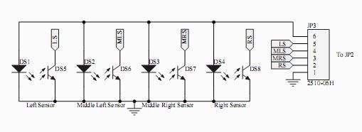
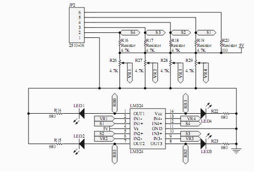
Yes, you need to tune the VR to set a threshold value for the LM324 comparator. Comparator will give '1' or '0' depending on the comparison result between the threshold and IR sensor's reading.

triptych2008 WROTE:to program the pic, using the UIC00A is enuff right? dont need to install mplab or picc lite if i use the sample source code...

Yes, UIC00A is enough for the job. MPLAB and PICC compiler are used for modification of the source code.

triptych2008 WROTE:last, in the sample source code for pr23, how u get the speed of the motor to be 255, 180 etc..

I don't really understand your question. I assume you are asking why is the speed being set to 0-255 instead of other value. Actually the value is based on the PWM module in PIC. Since the PWM module in 16F877A is using Timer 2, which is the 8-bit timer, so the max value is 255. <<Please refer to my next post>> That means the duty cycle of the PWM can be set from 0 to 255 and this PWM value will control the speed of the motor. The higher the duty cycle, the faster the speed and vice versa. You can read PIC16F877A datasheet, section "Capture/Compare/PWM Modules" for more details. Inside the sample source code, you may get the motor PWM configuration in init() function.
User avatar
sich
Moderator
 
Posts: 603
Joined: Tue Apr 21, 2009 2:15 pm

Re: PR23 question

Postby sich » Fri Jul 24, 2009 12:53 pm

I've made a mistake in my previous post! Sorry about that and thanks to my friend who pointed it out!

PWM for PIC16F877A has 10 bits resolution NOT 8 bits. Timer 2, which is 8 bits timer, is concatenated with 2 bits internal clock or 2 bits prescaler to create the 10 bits resolution PWM duty cycle. This new 10 bits timer is compared with the concatenation of CCPR1L (8 bits) and CCP1CON<5:4> (2 bits). About the PWM period, PR2 (period register) is compared directly with Timer 2 (8 bits). So it has only 8 bits resolution.

The reason i thought the PWM duty cycle has only 8 bits resolution is because I often use CCPR1L only to control the PWM duty cycle and ignore the two bits from CCP1CON<5:4>. That yields 8 bits resolution for my case. After creating function to initiate the configuration in 8 bits, I only need to call the function when I'm using PWM for my projects. Therefore I forgot that actually It should be more than 8 bits after some time. Haha...=P Sorry for giving wrong info earlier!

So for PR23, I guess the project builder also ignores the 2 bits from CCP1CON<5:4> in order to make the source code becomes simpler (no need to do concatenate operation). Then the max speed value is up to 8 bits which is 255 only.
~> How to ask QUESTIONS the SMART way in FORUM? <~
User avatar
sich
Moderator
 
Posts: 603
Joined: Tue Apr 21, 2009 2:15 pm

Next

Return to DIY Project Set

Who is online

Users browsing this forum: No registered users and 13 guests

cron