- CODE: SELECT_ALL_CODE
The C Main program code "main.c".
#ifndef _XTAL_FREQ
// Unless specified elsewhere, 4MHz system frequency is assumed
#define _XTAL_FREQ 10000000
#endif include <pic.h>
#include <htc.h>
__CONFIG(0x3F3A);
#include <stdlib.h>
#include <stdio.h>
#include "lcd.h"
#include "main.h"

volatile unsigned char data[91];
unsigned char buf1[16];
unsigned char buf2[16];

static void interrupt isr(void)
{
unsigned char d;
int i;
if(RCIF)
{
d=RCREG;
RCIF=0;
//removing any garbage that has been received as part of UART receive
if((d >64 && d <91) ||(d>47 && d<58) || d==36 || d==46 || d==42 || d==44 || d==13 || d==10) //|| d==44,36 dollar
{
for(i=0;i<90;i++)
{
data[i]=data[i+1];
}
if(d== 13 || d==10)
data[90]=59;
else data[90]=d;

if(OERR)
{
/*reset USART receiver logic to clear OERR*/
CREN=0; CREN=1;
}
if(FERR)
{

}
}
}
}
void copyString(int i)
{
int j;
for(j=0;j<16;j++)
{
if(i+j+6 < 90)
buf1[j]=data[i+j];
if(i+j+22 <90)
buf2[j]=data[i+j+16];
}
}
//grabing the NMEA string by identifying the start
int getString()
{
int i;
for(i=0; i<80;i++)
{
if(data[i]==36 && data[i+1]==71 && data[i+2]==80)
{
if(data[i+3]==71 && data[i+4]==71 && data[i+5]==65 ) //GGA
{
copyString(i);
return 5;
}
else if(data[i+3]==71 && data[i+4]==83 && data[i+5]==65 ) //GSA
{
copyString(i);
return 6;
}
else if(data[i+3]==71 && data[i+4]==83 && data[i+5]==86 ) //GSV
{
copyString(i);
return 7;
}
else if(data[i+3]==82 && data[i+4]==77 && data[i+5]==67 ) //RMC
{
copyString(i);
return 8;
}

//return 1;
}
}
return 0;
}

void main(void)
{
const char s[] ="init ";

int i,retval;
retval=0;

/*setting all the unused pins to output. this is important
*/to minimise garbage in UART data. tie down all unused ports
* nothing should be floating*/

TRISA=0b00000000;;
TRISB=0b00000000;
TRISC=0b11000000;
TRISD=0b00000000;
TRISE=0b00000000;
OPTION=0b00000000;
ADCON1=0b00000110;//configures the functions of the port pins
INTCON=0b11000000;
PIE1=0b00100000;//Enable RX interrupt no RT interrupt
PORTA=0b00000000;
PORTB=0b00000000;
PORTC=0b00000000;
PORTD=0b00000000;
PORTE=0b00000000;

TXSTA=0b10100000;
RCSTA=0b10010000;
BRGH=1;
SPBRG=127; // this needs to be modified based on your crystal frequency. refer datasheet

// starting lcd and displaying welcome text
lcd_init();
lcd_goto(0);
lcd_puts(s);
// delaying for a few seconds for the GPS to start up
for(i=0;i<4;i++)
{
lcd_clear();
lcd_goto(0);
sprintf(buf1, "init %d", i);
lcd_puts(buf1);
mySDelay(4);
}

i=0;
for(;;)
{
if(i > 5)
retval =getString();
if (retval > 1)
{
PIE1=0b00000000; // stoping interrupts to fix display problems
lcd_clear();
lcd_goto(0);
lcd_puts(buf1);
lcd_goto(0x40);
lcd_puts(buf2);
i=0;
retval=0;
PIE1=0b00100000; // restarting interrupts
}

mySDelay(2);
i++;
}

}


void mySDelay(int n)
{
for(int j=0;j<n;j++)
{
__delay_ms(250);
}
}
Header code "main.h".
#ifndef   _MAIN_H_
#define _MAIN_H_

extern void mySDelay(int n);
void initGPS();
void readData(char[]);

#endif   /* _MAIN_H_ */
The C LCD driver "lcd.c".
/*
*/LCD interface example
*Uses routines from delay.c
*This code will interface to a standard LCD controller
*like the Hitachi HD44780. It uses it in 4 bit mode, with
*the hardware connected as follows (the standard 14 pin
*LCD connector is used):
*
*PORTB bits 0-3 are connected to the LCD data bits 4-7 (high nibble)
*PORTA bit 3 is connected to the LCD RS input (register select)
*PORTA bit 1 is connected to the LCD EN bit (enable)
*
*To use these routines, set up the port I/O (TRISA, TRISD) then
*call lcd_init(), then other routines as required.
*
*/

#ifndef _XTAL_FREQ
// Unless specified elsewhere, 4MHz system frequency is assumed
#define _XTAL_FREQ 10000000
#endif include<htc.h>
#include   "lcd.h"

#define   LCD_CL RD6//RC7
#define   LCD_DT RD5//RC6
#define LCD_EN RD4//RC5


#define   LCD_STROBE()((LCD_EN = 1),(LCD_EN=0))
#define   CLOCK_STROBE()((LCD_CL = 0),(LCD_CL=1))

/* write a byte to the LCD in 4 bit mode */

void cd_writenibble(unsigned char c, unsigned char command)
{
LCD_DT=command;
CLOCK_STROBE();
unsigned char p =0x01;
for(int i=0; i<8;i++)
{
if(c & p) LCD_DT=1; else LCD_DT=0;
CLOCK_STROBE();
p=p<<1;
}
for(int i=0; i<3;i++)
{
LCD_DT=0;
CLOCK_STROBE();
}
}

void cd_write(unsigned char c, unsigned char command)
{
__delay_us(40);
lcd_writenibble( c,command);
LCD_STROBE();
}

/*
*/Clear and home the LCD
*/

void cd_clear(void)
{
lcd_write(0x01,0);
__delay_ms(3);
}

/* write a string of chars to the LCD */

void cd_puts(const char * s)
{
// write characters
int i=0;
while(*s && i <16)
{
lcd_write(*s++,1);
i++;
}
}

/* write one character to the LCD */

void cd_putch(char c)
{
// write characters
lcd_write( c ,1);
}


/*
*/Go to the specified position
*/

void cd_goto(unsigned char pos)
{
lcd_write(0x80+pos,0);
}

/* initialise the LCD - put into 4 bit mode */
void lcd_init()
{
char init_value;


init_value = 0x30;
TRISD=0;
LCD_CL = 0;
LCD_EN = 0;
LCD_DT = 0;


//LCD_DATA=0x00;
__delay_ms(35);
__delay_ms(15);// wait 15mSec after power applied,
lcd_writenibble(init_value,0);
LCD_STROBE();
__delay_ms(5);
LCD_STROBE();
__delay_us(200);
LCD_STROBE();
__delay_us(200);
lcd_writenibble( 0x30,0);// Eight bit mode
LCD_STROBE();
__delay_ms(2);
lcd_write(0x38,0); // Set interface length
__delay_ms(2);
lcd_write(0x0C,0); // Display On, Cursor OFF, Cursor Blink OFF
lcd_clear();// Clear screen
lcd_write(0x06,0); // Set entry Mode
}
LCD Header "lcd.h".
/*
*/LCD interface header file
*See lcd.c for more info
*/

/* write a byte to the LCD in 4 bit mode */

extern void lcd_write(unsigned char,unsigned char);

/* Clear and home the LCD */

extern void lcd_clear(void);

/* write a string of characters to the LCD */

extern void lcd_puts(const char * s);

/* Go to the specified position */

extern void lcd_goto(unsigned char pos);

/* intialize the LCD - call before anything else */

extern void lcd_init(void);

extern void lcd_putch(char);
extern void lcd_putdebugstr(const char * s);

/*Set the cursor position */

#define   lcd_cursor(x)
lcd_write(((x)&0x7F)|0x80)
lcd view only black box in second row
17 posts
• Page 1 of 2 • 1, 2
lcd view only black box in second row
![]() by ax2030 » Sun Feb 24, 2013 2:35 pm
by ax2030 » Sun Feb 24, 2013 2:35 pm
i tried to interface gps module skm53 with pic 16f877A. ut all i got is only black screen on the second line.im using (16x2) LCD. below is my code, am i missing something?
- ax2030

- Posts: 6
- Joined: Sun Feb 24, 2013 2:27 pm
Re: lcd view only black box in second row
![]() by robosang » Mon Feb 25, 2013 9:55 pm
by robosang » Mon Feb 25, 2013 9:55 pm
Is not possible for us to go through your code, a photo of LCD will be helpful.
- robosang

- Posts: 1239
- Joined: Wed Jun 10, 2009 5:37 pm
Re: lcd view only black box in second row
![]() by yonghui » Tue Feb 26, 2013 9:23 am
by yonghui » Tue Feb 26, 2013 9:23 am
hi
u can try to check the lcd alone 1st before connect and do communication with the gps module.
so jus send string to lcd see if it can function properly.
u can try to check the lcd alone 1st before connect and do communication with the gps module.
so jus send string to lcd see if it can function properly.
thanks®ards,
yh
yh
- yonghui

- Posts: 732
- Joined: Mon Sep 28, 2009 3:27 pm
Re: lcd view only black box in second row
![]() by ax2030 » Tue Feb 26, 2013 11:39 am
by ax2030 » Tue Feb 26, 2013 11:39 am
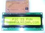
this is not my lcd..but the display is same with my lcd..
- Attachments
-
- 28_1297352019.jpg (37.78 KiB) Viewed 5394 times
- ax2030
- Posts: 6
- Joined: Sun Feb 24, 2013 2:27 pm
Re: lcd view only black box in second row
![]() by robosang » Tue Feb 26, 2013 12:02 pm
by robosang » Tue Feb 26, 2013 12:02 pm
that is the 1st row, not the 2nd row 
This indicate the LCD is not initialized, please check your connection and pin assignment. and check the LCD section, I am sure there is something wrong.
How is the LCD being connected to microcontroller, list it out.
This indicate the LCD is not initialized, please check your connection and pin assignment. and check the LCD section, I am sure there is something wrong.
How is the LCD being connected to microcontroller, list it out.
- robosang
- Posts: 1239
- Joined: Wed Jun 10, 2009 5:37 pm
Re: lcd view only black box in second row
![]() by ax2030 » Tue Feb 26, 2013 7:42 pm
by ax2030 » Tue Feb 26, 2013 7:42 pm
robosang WROTE:that is the 1st row, not the 2nd row
This indicate the LCD is not initialized, please check your connection and pin assignment. and check the LCD section, I am sure there is something wrong.
How is the LCD being connected to microcontroller, list it out.
- Attachments
-
- ax2030
- Posts: 6
- Joined: Sun Feb 24, 2013 2:27 pm
Re: lcd view only black box in second row
![]() by shahrul » Tue Feb 26, 2013 8:33 pm
by shahrul » Tue Feb 26, 2013 8:33 pm
Why you use 74147 interface? You can connect directly to PIC pin, still have many pin not use.
-
shahrul 
- Posts: 812
- Joined: Sat May 16, 2009 9:54 pm
- Location: Selangor
Re: lcd view only black box in second row
![]() by robosang » Tue Feb 26, 2013 10:06 pm
by robosang » Tue Feb 26, 2013 10:06 pm
Woh....
My advise, try to use direct connection as suggested by shahrul, save your pain and time a lot.
Out of curiosity, what is the function of 74174 for?
BTW, try to do the circuit part by part and also the program too, you are beginner, not expert yet. So learn slowly.
My advise, try to use direct connection as suggested by shahrul, save your pain and time a lot.
Out of curiosity, what is the function of 74174 for?
BTW, try to do the circuit part by part and also the program too, you are beginner, not expert yet. So learn slowly.
- robosang
- Posts: 1239
- Joined: Wed Jun 10, 2009 5:37 pm
Re: lcd view only black box in second row
![]() by shahrul » Tue Feb 26, 2013 11:23 pm
by shahrul » Tue Feb 26, 2013 11:23 pm
You can use shift register if you are out of pin to use, but only if you have many experience with LCD.
This is example use shift register into LCD to save no of pin using Arduino Uno.
This is example use shift register into LCD to save no of pin using Arduino Uno.
-
shahrul - Posts: 812
- Joined: Sat May 16, 2009 9:54 pm
- Location: Selangor
Re: lcd view only black box in second row
![]() by ax2030 » Wed Feb 27, 2013 12:49 am
by ax2030 » Wed Feb 27, 2013 12:49 am
if i connect the pic direct to the lcd...which part of code that i need to adjust?? which pic pin needed to connect to the lcd...i'm only beginner in this..
- ax2030
- Posts: 6
- Joined: Sun Feb 24, 2013 2:27 pm
17 posts
• Page 1 of 2 • 1, 2
Who is online
Users browsing this forum: No registered users and 27 guests