K.I.T.T. (Replica)??? realy complicated project at a start..

Works done? Proud of it? Show off here! Let's see what you've built can help inspire others.

K.I.T.T. (Replica)??? realy complicated project at a start..

Postby samuraiman » Fri Dec 23, 2011 11:01 pm

Project Name: K.I.T.T (Replica)
Author/Designer: Me
Project Description: K.I.T.T Replica???(Dont BOO me... just a start...) or something base on this idea using SK-40C + PIC 16F877A
Photo/Picture/Figure/Diagram/Flowchart: See Below
Compiler: PIC BASIC PRO
Source code: Upload later... just simple codes and still on the way to simplify them
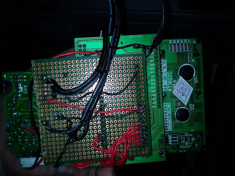
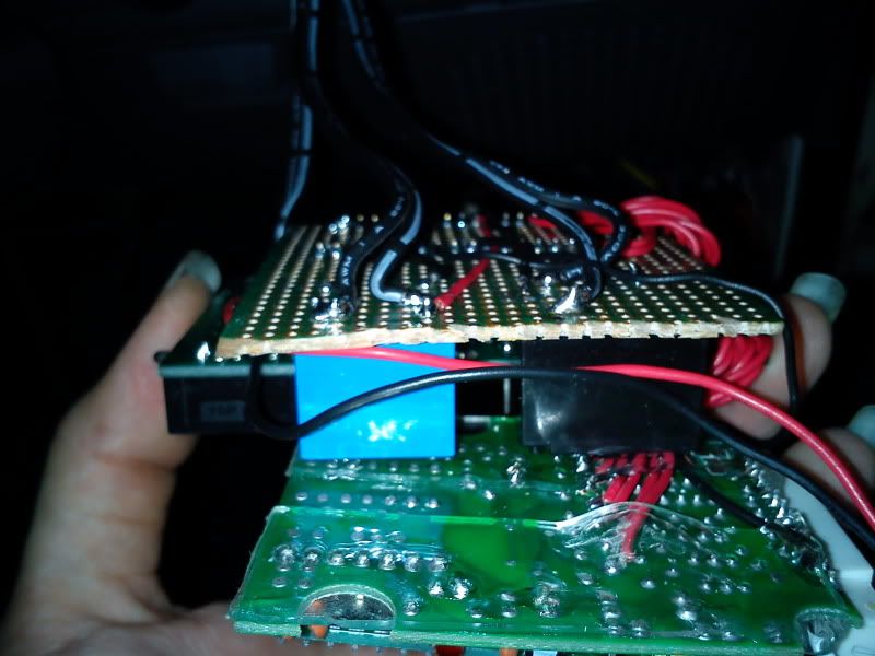
Schematics & PCB Docs: See below pic... just a test circuit...
Hardware Drawing: Drawing??? no... got only photos...

This is My new (free time) project...

i had just learn to program microcontroller in my college by using Microcode studio... the codes are slightly different from c programming... as most of the sample codes i can get online and in cytron tutorial sites are c programming codes, i had to study to program using c language... this is far more complicated from the c++ i had studies before(but basic is the same)...

i had this idea to start this project after i had installed a new car alarm system with engine push start button into my car... yes... i install myself... the problem is my engine is modified and using custom ecu (MicroTech system)... this ecu does't have auto chock system that makes the engine very hard to be started especially on morning... i need to crank at least 3 to 4 sec to make the engine starts... the alarm set with push start will only crank for about 2.5 sec when i push the button and this makes me have to push again to start the engine... some times i had to push until three to four times to start the engine...

this is a basic function that solve the engine starting problem... as the microcontroller i used has many ports that i think on adding some features into it and also some bling bling effects(hahaha)...

there are many functions i plan to put into this project...
1. Crank the engine not base on the time set, but base on the sensor
this means that the microcontroller will act base on the RPM of the engine... the engine will stop cranking when the microcontroller sense the rpm
of the engine is more than 500rpm...

2. Auto engine recovery...
the system will crank the engine 1 sec after the engine dead when driving or at traffic light(the microcontroller senses 0rpm)... for manual
transmission car, a switch will be placed at the clutch pedal to make sure that the clutch is free before the engine is cranked...

3. Control the setting of the engine
i like the cruise mode of old KITT and also new KITT... i plan to make the microcontroller change the fuel map in my ecu(already set in ecu) and
also the boost controller setting... for "Normal Cruise", the microcontroller have to change the fuel map to economy one and set the boost
controller to abt 0.6bar... For "Attact Mode", the microcontroller have to set the fuel map to a more richer fuel map and set the electrioic boost
controller to 1bar... For "Attact Mode II" the microcintroller have to set the fuel map (actually is the same fuel map as 1 bar boost) and set the
elctronic boost controller to 1.2 bar...

4. K.I.T.T Sound and Light Effect...
For fun purpose, i think on to put the original K.I.T.T. sound effect such as the scanner sound and the kitt voice ... got saw the sound recorder
chip in cytron websites but haven't studied the datasheet yet...

5.??????
Will add when got ideas...

Below is the video of the beta version of my project:


this is the automatic start function once the engine start button was pressed... the system will delay the crank process 1 to 2 seconds and make the cranking time longer... the first tick-tok sound(relay ticking) is the original relay(alarm system) to crank the engine, but i revert it into the microcontroller as input to start the engine... the second tik-tok(relay ticking sound) is the 5v relay drive by the microcontroller to crank the engine... of course... microcontroller --> 5v relay --> 12v automotive relay (high current) --> starter...


this is the manual start function... the button on the pcb has to be pressed to crank the engine... the same button can be pressed to crank the engine once the engine died on the road...


this is the camera light off version in the dark with the kitt scanner light effect... tried to use software pwm and the result is slightly unsatisfied... will try another way to perform pwm for the light bar...

Image

Image


Some of the codes i copy from the samples get from my lecturer(most of the codes i had to figure out myself especially the pwm parts... my lecture says my method is abit wrong...hehe)... i had to modify the codes to suit the SK-40C especially the lcd ports... somepart still got the descriptions and i m lazy to delete them... lazy also that i always have to switch between Pic kit 2 and MicrocodeStudio so just use bootloader... haha...

CODE: SELECT_ALL_CODE
define loader_used 1
define OSC 20

trisa=%00000000
porta=%00000000
trisb=%00000101
portb=%00000000
trisc=%00000000
Portc=%00000000
trisd=%00000000
portd=%00000000
           
DEFINE LCD_DREG PORTd   ' Set LCD Data port to Port D of MCU
DEFINE LCD_DBIT 4      ' Set starting Data bit (0)
DEFINE LCD_RSREG PORTb   ' Set LCD Register Select port
DEFINE LCD_RSBIT 4      ' Set LCD Register Select bit
DEFINE LCD_EREG PORTb   ' Set LCD Enable port
DEFINE LCD_EBIT 5      ' Set LCD Enable bit.
DEFINE LCD_BITS 4      ' Set LCD bus size (4 bits)
i var byte
cl  var byte
ST VAR BYTE
ST = 0

main:
                                                         
        high porta.0
        BUTTON portb.0,0,255,1,cl,1,ON_ENGINE
         
    if ST = 0 then       
        LCDOUT  $FE,1,  "    K.I.T.T.    "
        LCDOUT  $FE,$C0,  "  VER 2.0 BETA  "
        PAUSE 1000
        ST = 1
        endif
                     
    IF ST = 1 THEN
        LCDOUT  $FE,1,  "   INITIALIZE   "
        PAUSE 100
        ST = 1
        endif
                   
    IF ST = 3 THEN
        portc=%00000000
        portd=%00000000
        LCDOUT  $FE,1,  "HYPERDRIVEngine"
        LCDOUT  $FE,$C0,  "   ACTIVATED   "
        PAUSE 4000
        ST = 4
        endif
       
    if ST = 4  then
        LCDOUT  $FE,1,  "    SCANNER     "
        LCDOUT  $FE,$C0,  "   ACTIVATED   "
        pause 2000
        ST = 5
        endif
       
    if st = 5 then
   
       
        LCDOUT  $FE,1,  "     NORMAL     "
        LCDOUT  $FE,$C0,  "     CRUISE     "
        pause 1
       
        for i = 0 to 255 step 4
        BUTTON portb.0,0,255,1,cl,1,ON_ENGINE
        pwm portc.0,i,1
        pwm portc.1,0,1
        pwm portc.2,0,1
        pwm portc.3,0,1
        pwm portc.4,0,1
        pwm portc.5,0,1
        pwm portd.0,0,1
        pwm portd.1,0,1
        next i
        for i = 0 to 255 step 4
        BUTTON portb.0,0,255,1,cl,1,ON_ENGINE
        pwm portc.0,255,1
        pwm portc.1,i,1
        pwm portc.2,0,1
        pwm portc.3,0,1
        pwm portc.4,0,1
        pwm portc.5,0,1
        pwm portd.0,0,1
        pwm portd.1,0,1
        next i
        for i = 0 to 255 step 4
        BUTTON portb.0,0,255,1,cl,1,ON_ENGINE
        pwm portc.0,255,1
        pwm portc.1,255,1
        pwm portc.2,i,1
        pwm portc.3,0,1
        pwm portc.4,0,1
        pwm portc.5,0,1
        pwm portd.0,0,1
        pwm portd.1,0,1
        next i
        for i = 0 to 255 step 4
        BUTTON portb.0,0,255,1,cl,1,ON_ENGINE
        pwm portc.0,255,1
        pwm portc.1,255,1
        pwm portc.2,255,1
        pwm portc.3,i,1
        pwm portc.4,0,1
        pwm portc.5,0,1
        pwm portd.0,0,1
        pwm portd.1,0,1
        next i
        for i = 0 to 255 step 4
        BUTTON portb.0,0,255,1,cl,1,ON_ENGINE
        pwm portc.0,255,1
        pwm portc.1,255,1
        pwm portc.2,255,1
        pwm portc.3,255,1
        pwm portc.4,i,1
        pwm portc.5,0,1
        pwm portd.0,0,1
        pwm portd.1,0,1
        next i
        for i = 0 to 255 step 4             
        BUTTON portb.0,0,255,1,cl,1,ON_ENGINE     
        pwm portc.0,255,1
        pwm portc.1,255,1
        pwm portc.2,255,1
        pwm portc.3,255,1
        pwm portc.4,255,1
        pwm portc.5,i,1
        pwm portd.0,0,1
        pwm portd.1,0,1
        next i
        for i = 0 to 255 step 4             
        BUTTON portb.0,0,255,1,cl,1,ON_ENGINE     
        pwm portc.0,255,1
        pwm portc.1,255,1
        pwm portc.2,255,1
        pwm portc.3,255,1
        pwm portc.4,255,1
        pwm portc.5,255,1
        pwm portd.0,i,1
        pwm portd.1,0,1
        next i
        for i = 0 to 255 step 4             
        BUTTON portb.0,0,255,1,cl,1,ON_ENGINE     
        pwm portc.0,255,1
        pwm portc.1,255,1
        pwm portc.2,255,1
        pwm portc.3,255,1
        pwm portc.4,255,1
        pwm portc.5,255,1
        pwm portd.0,255,1
        pwm portd.1,i,1
        next i
        for i = 255 to 0 step -4             
        BUTTON portb.0,0,255,1,cl,1,ON_ENGINE       
        pwm portc.0,i,1
        pwm portc.1,255,1
        pwm portc.2,255,1
        pwm portc.3,255,1
        pwm portc.4,255,1
        pwm portc.5,255,1
        pwm portd.0,255,1
        pwm portd.1,255,1
        next i
        for i = 255 to 0 step -4             
        BUTTON portb.0,0,255,1,cl,1,ON_ENGINE       
        pwm portc.0,0,1
        pwm portc.1,i,1
        pwm portc.2,255,1
        pwm portc.3,255,1
        pwm portc.4,255,1
        pwm portc.5,255,1
        pwm portd.0,255,1
        pwm portd.1,255,1
        next i
        for i = 255 to 0 step -4             
        BUTTON portb.0,0,255,1,cl,1,ON_ENGINE       
        pwm portc.0,0,1
        pwm portc.1,0,1
        pwm portc.2,i,1
        pwm portc.3,255,1
        pwm portc.4,255,1
        pwm portc.5,255,1
        pwm portd.0,255,1
        pwm portd.1,255,1
        next i
        for i = 255 to 0 step -4             
        BUTTON portb.0,0,255,1,cl,1,ON_ENGINE       
        pwm portc.0,0,1
        pwm portc.1,0,1
        pwm portc.2,0,1
        pwm portc.3,i,1
        pwm portc.4,255,1
        pwm portc.5,255,1
        pwm portd.0,255,1
        pwm portd.1,255,1
        next i
        for i = 255 to 0 step -4             
        BUTTON portb.0,0,255,1,cl,1,ON_ENGINE       
        pwm portc.0,0,1
        pwm portc.1,0,1
        pwm portc.2,0,1
        pwm portc.3,0,1
        pwm portc.4,i,1
        pwm portc.5,255,1
        pwm portd.0,255,1
        pwm portd.1,255,1
        next i
        for i = 255 to 0 step -4
        BUTTON portb.0,0,255,1,cl,1,ON_ENGINE                   
        pwm portc.0,0,1
        pwm portc.1,0,1
        pwm portc.2,0,1
        pwm portc.3,0,1
        pwm portc.4,0,1
        pwm portc.5,i,1
        pwm portd.0,255,1
        pwm portd.1,255,1
        next i
        for i = 255 to 0 step -4             
        BUTTON portb.0,0,255,1,cl,1,ON_ENGINE       
        pwm portc.0,0,1
        pwm portc.1,0,1
        pwm portc.2,0,1
        pwm portc.3,0,1
        pwm portc.4,0,1
        pwm portc.5,0,1
        pwm portd.0,i,1
        pwm portd.1,255,1
        next i
        for i = 255 to 0 step -4             
        BUTTON portb.0,0,255,1,cl,1,ON_ENGINE       
        pwm portc.0,0,1
        pwm portc.1,0,1
        pwm portc.2,0,1
        pwm portc.3,0,1
        pwm portc.4,0,1
        pwm portc.5,0,1
        pwm portd.0,0,1
        pwm portd.1,i,1
        next i
        for i = 0 to 255 step 20
        BUTTON portb.0,0,255,1,cl,1,ON_ENGINE
        pwm portc.0,0,1
        pwm portc.1,0,1
        pwm portc.2,0,1
        pwm portc.3,0,1
        pwm portc.4,0,1
        pwm portc.5,0,1
        pwm portd.0,0,1
        pwm portd.1,i,1
        next i
        for i = 0 to 255 step 20
        BUTTON portb.0,0,255,1,cl,1,ON_ENGINE
        pwm portc.0,0,1
        pwm portc.1,0,1
        pwm portc.2,0,1
        pwm portc.3,0,1
        pwm portc.4,0,1
        pwm portc.5,0,1
        pwm portd.0,i,1
        pwm portd.1,255,1
        next i
        for i = 0 to 255 step 20
        BUTTON portb.0,0,255,1,cl,1,ON_ENGINE
        pwm portc.0,0,1
        pwm portc.1,0,1
        pwm portc.2,0,1
        pwm portc.3,0,1
        pwm portc.4,0,1
        pwm portc.5,i,1
        pwm portd.0,255,1
        pwm portd.1,255,1
        next i
        for i = 0 to 255 step 20
        BUTTON portb.0,0,255,1,cl,1,ON_ENGINE
        pwm portc.0,0,1
        pwm portc.1,0,1
        pwm portc.2,0,1
        pwm portc.3,0,1
        pwm portc.4,i,1
        pwm portc.5,255,1
        pwm portd.0,255,1
        pwm portd.1,255,1
        next i
        for i = 0 to 255 step 20
        BUTTON portb.0,0,255,1,cl,1,ON_ENGINE
        pwm portc.0,0,1
        pwm portc.1,0,1
        pwm portc.2,0,1
        pwm portc.3,i,1
        pwm portc.4,255,1
        pwm portc.5,255,1
        pwm portd.0,255,1
        pwm portd.1,255,1
        next i
        for i = 0 to 255 step 20
        BUTTON portb.0,0,255,1,cl,1,ON_ENGINE
        pwm portc.0,0,1
        pwm portc.1,0,1
        pwm portc.2,i,1
        pwm portc.3,255,1
        pwm portc.4,255,1
        pwm portc.5,255,1
        pwm portd.0,255,1
        pwm portd.1,255,1
        next i
        for i = 0 to 255 step 20
        BUTTON portb.0,0,255,1,cl,1,ON_ENGINE
        pwm portc.0,0,1
        pwm portc.1,i,1
        pwm portc.2,255,1
        pwm portc.3,255,1
        pwm portc.4,255,1
        pwm portc.5,255,1
        pwm portd.0,255,1
        pwm portd.1,255,1
        next i
        for i = 0 to 255 step 20
        BUTTON portb.0,0,255,1,cl,1,ON_ENGINE
        pwm portc.0,i,1
        pwm portc.1,255,1
        pwm portc.2,255,1
        pwm portc.3,255,1
        pwm portc.4,255,1
        pwm portc.5,255,1
        pwm portd.0,255,1
        pwm portd.1,255,1
        next i
        for i = 255 to 0 step -20           
        BUTTON portb.0,0,255,1,cl,1,ON_ENGINE       
        pwm portc.0,255,1
        pwm portc.1,255,1
        pwm portc.2,255,1
        pwm portc.3,255,1
        pwm portc.4,255,1
        pwm portc.5,255,1
        pwm portd.0,255,1
        pwm portd.1,i,1
        next i
        for i = 255 to 0 step -20           
        BUTTON portb.0,0,255,1,cl,1,ON_ENGINE       
        pwm portc.0,255,1
        pwm portc.1,255,1
        pwm portc.2,255,1
        pwm portc.3,255,1
        pwm portc.4,255,1
        pwm portc.5,255,1
        pwm portd.0,i,1
        pwm portd.1,0,1
        next i
        for i = 255 to 0 step -20           
        BUTTON portb.0,0,255,1,cl,1,ON_ENGINE       
        pwm portc.0,255,1
        pwm portc.1,255,1
        pwm portc.2,255,1
        pwm portc.3,255,1
        pwm portc.4,255,1
        pwm portc.5,i,1
        pwm portd.0,0,1
        pwm portd.1,0,1
        next i
        for i = 255 to 0 step -20           
        BUTTON portb.0,0,255,1,cl,1,ON_ENGINE       
        pwm portc.0,255,1
        pwm portc.1,255,1
        pwm portc.2,255,1
        pwm portc.3,255,1
        pwm portc.4,i,1
        pwm portc.5,0,1
        pwm portd.0,0,1
        pwm portd.1,0,1
        next i
        for i = 255 to 0 step -20           
        BUTTON portb.0,0,255,1,cl,1,ON_ENGINE       
        pwm portc.0,255,1
        pwm portc.1,255,1
        pwm portc.2,255,1
        pwm portc.3,i,1
        pwm portc.4,0,1
        pwm portc.5,0,1
        pwm portd.0,0,1
        pwm portd.1,0,1
        next i
        for i = 255 to 0 step -20           
        BUTTON portb.0,0,255,1,cl,1,ON_ENGINE       
        pwm portc.0,255,1
        pwm portc.1,255,1
        pwm portc.2,i,1
        pwm portc.3,0,1
        pwm portc.4,0,1
        pwm portc.5,0,1
        pwm portd.0,0,1
        pwm portd.1,0,1
        next i
        for i = 255 to 0 step -20           
        BUTTON portb.0,0,255,1,cl,1,ON_ENGINE       
        pwm portc.0,255,1                   
        pwm portc.1,i,1
        pwm portc.2,0,1
        pwm portc.3,0,1
        pwm portc.4,0,1
        pwm portc.5,0,1
        pwm portd.0,0,1
        pwm portd.1,0,1
        next i
        for i = 255 to 0 step -20           
        BUTTON portb.0,0,255,1,cl,1,ON_ENGINE       
        pwm portc.0,i,1
        pwm portc.1,0,1
        pwm portc.2,0,1
        pwm portc.3,0,1
        pwm portc.4,0,1
        pwm portc.5,0,1
        pwm portd.0,0,1
        pwm portd.1,0,1
        next i
       
        endif
       
    goto main
   
ON_ENGINE:
    low porta.0
    LCDOUT  $FE,1,  "   ACTIVATING   "
    PAUSE 1000
    LCDOUT  $FE,1,  "   HYPERDRIVE   "
    LCDOUT  $FE,$C0,  "     ENGINE     "
    portc=%00111111
    portd=%00000011
    pause 2000
    ST = 3
    goto main
end
User avatar
samuraiman
Freshie
 
Posts: 7
Joined: Fri Dec 23, 2011 7:57 pm

Re: K.I.T.T. (Replica)??? realy complicated project at a sta

Postby ober » Sat Dec 24, 2011 1:24 pm

samuraiman, woh! This is great work! Keep it up, let me send the link to our facebook admin and share it. Again, looking forward for the next stage. :D
Ober Choo
Cytron Technologies Sdn Bhd
www.cytron.com.my
User avatar
ober
Moderator
 
Posts: 1486
Joined: Wed Apr 15, 2009 1:03 pm

Re: K.I.T.T. (Replica)??? realy complicated project at a sta

Postby ABSF » Sun Dec 25, 2011 7:37 am

This is a major undertaking you've done here. I would give you a big hand for encouragement! ;) Do keep up and further improve it.....

Though I am not much of a mechanic. I am interested in how you did it. I am also learning PICBasic Pro and thought your project might help me get deeper into this language. Is your codes opened source or you intend to keep it to yourself?

Please PM me in private if you intend to share the source....Thanks

Allen
The next war will determine NOT who is right BUT what is left.
User avatar
ABSF
Professional
 
Posts: 810
Joined: Wed Nov 10, 2010 9:32 am
Location: E Malaysia

Re: K.I.T.T. (Replica)??? realy complicated project at a sta

Postby samuraiman » Sun Dec 25, 2011 12:12 pm

ABSF WROTE:This is a major undertaking you've done here. I would give you a big hand for encouragement! ;) Do keep up and further improve it.....

Though I am not much of a mechanic. I am interested in how you did it. I am also learning PICBasic Pro and thought your project might help me get deeper into this language. Is your codes opened source or you intend to keep it to yourself?

Please PM me in private if you intend to share the source....Thanks

Allen


Actually i just use simple 'if then"...

post the codes and hope some pros will help me to simplify and make it better...

will do some modification on the pwm parts to make the leds on and off smoother and put the pwm parts into sub XX(forget how to mention) using gosub...

the problem is i m just a newbie in the programming and need much of time to find codes and try the codes...
User avatar
samuraiman
Freshie
 
Posts: 7
Joined: Fri Dec 23, 2011 7:57 pm

Re: K.I.T.T. (Replica)??? realy complicated project at a sta

Postby ABSF » Sun Dec 25, 2011 4:14 pm

So your Port D and Port B are used for LCD. Your button is connected to Port A.0. And your LEDs are connected to PortC. BTW how did you drive your LED? Transistors or ULN2803?

Here I did a little crack to reduce the first 8 FOR/NEXT loops to just one. The ARRAY[64] that I defined might be reused if you think a bit hard. Here's the code

CODE: SELECT_ALL_CODE
k VAR byte[64]
k[0]=i:k[1]=0:k[2]=0:k[3]=0:k[4]=0:k[5]=0:k[6]=0:k[7]=0
k[8]=255:k[9]=i:k[10]=0:k[11]=0:k[12]=0:k[13]=0:k[14]=0:k[15]=0
k[16]=255:k[17]=255:k[18]=i:k[19]=0:k[20]=0:k[21]=0:k[22]=0:k[23]=0
k[24]=255:k[25]=255:k[26]=255:k[27]=i:k[28]=0:k[29]=0:k[30]=0:k[31]=0
k[32]=255:k[33]=255:k[34]=255:k[35]=255:k[36]=i:k[37]=0:k[38]=0:k[39]=0
k[40]=255:k[41]=255:k[42]=255:k[43]=255:k[44]=255:k[45]=i:k[46]=0:k[47]=0
k[48]=255:k[49]=255:k[50]=255:k[51]=255:k[52]=255:k[53]=255:k[54]=i:k[55]=0
k[56]=255:k[57]=255:k[58]=255:k[59]=255:k[60]=255:k[61]=255:k[62]=255:k[63]=i

for x=0 to 7

      for i = 0 to 255 step 4             
        BUTTON portb.0,0,255,1,cl,1,ON_ENGINE     
        pwm portc.0,k(x*8+0),1
        pwm portc.1,k(x*8+1),1
        pwm portc.2,k(x*8+2),1
        pwm portc.3,k(x*8+3),1
        pwm portc.4,k(x*8+4),1
        pwm portc.5,k(x*8+5),1
        pwm portd.0,k(x*8+6),1
        pwm portd.1,k(x*8+7),1
        next i

next x


There are some mistakes in my code and I have modified it. Above is the new codes...Still not sure if it will work or not........Allen
The next war will determine NOT who is right BUT what is left.
User avatar
ABSF
Professional
 
Posts: 810
Joined: Wed Nov 10, 2010 9:32 am
Location: E Malaysia

Re: K.I.T.T. (Replica)??? realy complicated project at a sta

Postby samuraiman » Sun Dec 25, 2011 5:09 pm

ABSF WROTE:So your Port D and Port B are used for LCD. Your button is connected to Port A.0. And your LEDs are connected to PortC. BTW how did you drive your LED? Transistors or ULN2803?

Here I did a little crack to reduce the first 8 FOR/NEXT loops to just one. The ARRAY[64] that I defined might be reused if you think a bit hard. Here's the code

CODE: SELECT_ALL_CODE
k VAR byte[64]
k[0]=i:k[1]=0:k[2]=0:k[3]=0:k[4]=0:k[5]=0:k[6]=0:k[7]=0
k[8]=255:k[9]=i:k[10]=0:k[11]=0:k[12]=0:k[13]=0:k[14]=0:k[15]=0
k[16]=255:k[17]=255:k[18]=i:k[19]=0:k[20]=0:k[21]=0:k[22]=0:k[23]=0
k[24]=255:k[25]=255:k[26]=255:k[27]=i:k[28]=0:k[29]=0:k[30]=0:k[31]=0
k[32]=255:k[33]=255:k[34]=255:k[35]=255:k[36]=i:k[37]=0:k[38]=0:k[39]=0
k[40]=255:k[41]=255:k[42]=255:k[43]=255:k[44]=255:k[45]=i:k[46]=0:k[47]=0
k[48]=255:k[49]=255:k[50]=255:k[51]=255:k[52]=255:k[53]=255:k[54]=i:k[55]=0
k[56]=255:k[57]=255:k[58]=255:k[59]=255:k[60]=255:k[61]=255:k[62]=255:k[63]=i

for x=0 to 7
for y=0 to 7

      for i = 0 to 255 step 4             
        BUTTON portb.0,0,255,1,cl,1,ON_ENGINE     
        pwm portc.0,k(x*8+y),1
        pwm portc.1,k(x*8+y),1
        pwm portc.2,k(x*8+y),1
        pwm portc.3,k(x*8+y),1
        pwm portc.4,k(x*8+y),1
        pwm portc.5,k(x*8+y),1
        pwm portd.0,k(x*8+y),1
        pwm portd.1,k(x*8+y),1
        next i

next y
next x


the two button on sk-40c is connected to portb.0 and portb.1,but i just use the button portb.0 together with a relay connected to this port serve as switch also... porta.0 as output to drive relay to crank start the engine... i use microcontroller to direct drive the relay by using vdd and put porta.0 to low state to on the relay... i tried to put porta.0 to high state on the relay but the current is not enough to power the relay...

i just study the array and haven't master this coding... that's why i have a long way to go... i cant find the example coding from internet and the coding give by my lecturer is just enough for my studies... most of the coding i have to study the c coding and tried to convert to microcode studio coding...

the led drivers i m using is the drivers used by the 霹雳游侠灯 bought from car acc shop... i study the pcb and found that the 霹雳游侠灯 is using 18 pins microcontroller with wireless module, so i just direct connect the portc and two portd to the 霹雳游侠灯 pcb and use it's leds too... basically is 8 transistors(donno the model because the thing is in my car now) to drive the leds and the leds is high power 食人鱼 led (sorry for the mandarin words in this english forum,but i really donno how to call these things in english language)...
User avatar
samuraiman
Freshie
 
Posts: 7
Joined: Fri Dec 23, 2011 7:57 pm

Re: K.I.T.T. (Replica)??? realy complicated project at a sta

Postby robosang » Wed Dec 28, 2011 9:07 am

Yeah! This is great project.

Just curious to know, where normally the car alarm system being installed? I have a old Proton Iswara and the alarm sometime works sometime not, want to repair it but don know where is the system being hidden, any idea?

Looking forward for more video. The LEDs light really nice! Kudos man!
robosang
Expert
 
Posts: 1239
Joined: Wed Jun 10, 2009 5:37 pm

Re: K.I.T.T. (Replica)??? realy complicated project at a sta

Postby ABSF » Wed Dec 28, 2011 10:12 am

robosang WROTE:Yeah! This is great project.

Just curious to know, where normally the car alarm system being installed? I have a old Proton Iswara and the alarm sometime works sometime not, want to repair it but don know where is the system being hidden, any idea?


If I am not mistaken, it should be on the driver position on your right foot near to the fuse box. It is in a small black plastic box about 4"x4" big. One of my remote controls was faulty and I intended to change the whole alarm system and EON said that I have to buy the new remotes for 100+ each as well and the total came to about 400+. So I duplicated my remote in a car accessories shop for 70.00 using the universal remote control and it worked well until now. :)

Allen
The next war will determine NOT who is right BUT what is left.
User avatar
ABSF
Professional
 
Posts: 810
Joined: Wed Nov 10, 2010 9:32 am
Location: E Malaysia

Re: K.I.T.T. (Replica)??? realy complicated project at a sta

Postby samuraiman » Wed Dec 28, 2011 10:56 pm

ABSF WROTE:
robosang WROTE:Yeah! This is great project.

Just curious to know, where normally the car alarm system being installed? I have a old Proton Iswara and the alarm sometime works sometime not, want to repair it but don know where is the system being hidden, any idea?


If I am not mistaken, it should be on the driver position on your right foot near to the fuse box. It is in a small black plastic box about 4"x4" big. One of my remote controls was faulty and I intended to change the whole alarm system and EON said that I have to buy the new remotes for 100+ each as well and the total came to about 400+. So I duplicated my remote in a car accessories shop for 70.00 using the universal remote control and it worked well until now. :)

Allen


Ya... it is beside the fuse box behind the 'cover with holes'... at first i tot that place is the place to put front speaker but when i first change the oem alarm system to 2 way alarm system and i saw workers at acc shop open that part n took a black box with 'nerves'(and mess all the wires inside that i hv to tidy up myself) then i know the alarm system of my car is in that part... i had now two alarm systems, one is Carvox King-Eagle two way alarm system and one is SPY Keyless Entry Engine Start Car Alarm... i separate the two alarm systems, one to control the car engine and another one control the center locking system... n in this project i m playing with SPY Keyless Entry Engine Start Car Alarm... 8-)
User avatar
samuraiman
Freshie
 
Posts: 7
Joined: Fri Dec 23, 2011 7:57 pm

Re: K.I.T.T. (Replica)??? realy complicated project at a sta

Postby Brian Griffin » Wed Dec 28, 2011 11:04 pm

That's a cool and innovative project you make. Thumbs up for this. :)
PIC - UIC00B from Cytron (replacement for my broken PICKit 2), Pickit 3, MikroC for PIC
dsPIC - MikroC for dsPIC, mikromedia board (dsPIC33)
AVR - AVR Dragon
Parallax - Prop tool
User avatar
Brian Griffin
Enthusiast
 
Posts: 403
Joined: Mon Jan 17, 2011 9:36 am

Next

Return to Project Showcase

Who is online

Users browsing this forum: No registered users and 29 guests