I would like to learn PIC, and i bought sk40c with a PIC18F4550.
from the cytron given sample tutorial, i had download the <PIC18F_USB Sample Source Code> and try to compile it to hex file by using MPLAB.
Here is the download code, i only exchange the the first line from #include<p18f4520.h> into #include<p18f4550.h> also cannot.
Anyone help me?
- CODE: SELECT_ALL_CODE
//==========================================================================
//   Author            : CYTRON TECHNOLOGIES SDN BHD
//   Project            : SK40C sample code for PIC18f4520
//   Project description      : Blink LED1 and LED2 like police car
//
//==========================================================================

//   include
//==========================================================================
#include<p18f4550.h>

//   configuration bit
//==========================================================================
#pragma   config OSC = HS            // HS oscillator
#pragma   config FCMEN = OFF         // Fail-Safe Clock Monitor disabled
#pragma   config IESO = OFF         // Oscillator Switchover mode disabled
#pragma   config PWRT = OFF         // PWRT disabled
#pragma   config BOREN = OFF         // Brown-out Reset disabled in hardware and software
#pragma   config WDT = OFF         // WDT disabled (control is placed on the SWDTEN bit)
#pragma   config MCLRE = ON         // MCLR pin enabled; RE3 input pin disabled
#pragma   config PBADEN = OFF         // PORTB<4:0> pins are configured as digital I/O on Reset
#pragma   config CCP2MX = PORTC         // CCP2 input/output is multiplexed with RC1
#pragma   config LVP = OFF         // Single-Supply ICSP disabled
#pragma   config XINST = OFF         // Extended Instruction Set

//   define
//==========================================================================
#define   LED1   LATBbits.LATB6
#define   LED2   LATBbits.LATB7

#define   SW1      PORTBbits.RB0
#define   SW2      PORTBbits.RB1

#define   XTAL_FREQ   20MHZ   /* Crystal frequency in MHz */

#define   MHZ   *1000L         /* number of kHz in a MHz */
#define   KHZ   *1            /* number of kHz in a kHz */

#if   XTAL_FREQ >= 12MHZ
   #define   DelayUs(x)   { unsigned char _dcnt; \
              _dcnt = (x)*((XTAL_FREQ)/(12MHZ)); \
              while(--_dcnt != 0) \
                 continue; }
#else
   #define   DelayUs(x)   { unsigned char _dcnt; \
              _dcnt = (x)/((12MHZ)/(XTAL_FREQ))|1; \
              while(--_dcnt != 0) \
                 continue; }
#endif

//   function prototype
//==========================================================================
void init(void);
void DelayMs(unsigned char);

//   global variable
//==========================================================================

//   main function
//==========================================================================
void main(void)
{
   unsigned char i;

   init();         // initialise PIC
   LED1 = 0;      // off LED1
   LED2 = 0;      // off LED2

   while(1)
   {
      for(i=8; i>0 ; i--)      // looping for 8 times (4 times blink)
      {
         LED1 ^= 1;         // toggle LED1
         DelayMs(110);      // delay 110ms
      }
      DelayMs(800);         // delay 800ms

      for(i=8; i>0 ; i--)      // looping for 8 times (4 times blink)
      {
         LED2 ^= 1;         // toggle LED2
         DelayMs(110);      // delay 110ms
      }
      DelayMs(800);         // delay 800ms

      while( !SW1 || !SW2 );   // Stop blinking if either SW1 or SW2 is being pressed
   }
}


//   functions
//==========================================================================
void init(void)   // initialise function
{
   //tris
   TRISBbits.TRISB0=1;      //configure PORTB I/O direction
   TRISBbits.TRISB1=1;      //configure PORTB I/O direction
   TRISBbits.TRISB6=0;      //configure PORTB I/O direction
   TRISBbits.TRISB7=0;      //configure PORTB I/O direction
}

void DelayMs(unsigned char cnt)   // delay function (mili second)
{
   #if   XTAL_FREQ <= 2MHZ
      do {
         DelayUs(996);
      } while(--cnt);
   #endif

   #if    XTAL_FREQ > 2MHZ
      unsigned char   i;
      do {
         i = 4;
         do {
            DelayUs(250);
         } while(--i);
      } while(--cnt);
   #endif
}
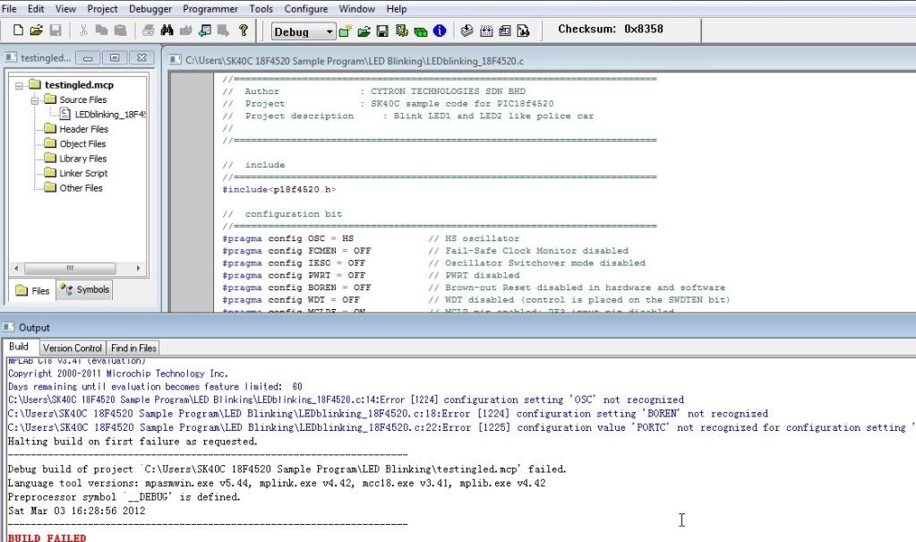
The error after compile is as below: