Stepper Motor Driver (L297+L298)

LINIX Brushless, VEXTA Brushless, RC Servo, DC Geared, Linear, Stepper, Tamiya.....

Stepper Motor Driver (L297+L298)

Postby Ffenixz » Sun Jan 23, 2011 1:58 am

Hello everyone. I just registered here. :D

Now onto my topic. I'm trying build a bipolar stepper motor driver which will drive a bipolar Linix Stepper Motor <link>. This driver will be based on L297 and L298 IC combination. I've seen the data sheet for L298 <link>. On page 8 of the data sheet, there's a sample schematic for this driver. We can see that L6210 Schottky diode bridge is placed in between the motor and L298 IC for circuit protection.

My question is, if I am to use individual diodes to replace the L6210 IC, must I use a 2A fast diode according to the data sheet or it is dependent on the motor winding current? Say for the motor that I am using above, it is rated at 0.4A. Am I good to go if I am to switch the 2A diode with a 1A diode (or any fast switcing diode with a forward current of > 0.4A for that matter) ?
User avatar
Ffenixz
Freshie
 
Posts: 5
Joined: Sun Jan 23, 2011 1:20 am

Re: Stepper Motor Driver (L297+L298)

Postby ABSF » Sun Jan 23, 2011 10:35 am

Ffenixz WROTE:My question is, if I am to use individual diodes to replace the L6210 IC, must I use a 2A fast diode according to the data sheet or it is dependent on the motor winding current? Say for the motor that I am using above, it is rated at 0.4A. Am I good to go if I am to switch the 2A diode with a 1A diode (or any fast switcing diode with a forward current of > 0.4A for that matter) ?


What is L6210, and what is its specs? What is the freq of the pulses sent to the stepper motor when it is running at max speed? The diodes are used for protecting the driver IC from the motor's back EMF.

I normally use 1N4007 or 1N4148 across my relay as they are slow speed devices. If your motor is running at 400mA at high speed, I think 1A 600V fast recovery diodes should be adequate. They only cost 25 cents each in Jalan Pasar. The 1000V ones are 30 cents each.

Allen
The next war will determine NOT who is right BUT what is left.
User avatar
ABSF
Professional
 
Posts: 810
Joined: Wed Nov 10, 2010 9:32 am
Location: E Malaysia

Re: Stepper Motor Driver (L297+L298)

Postby Ffenixz » Sun Jan 23, 2011 2:45 pm

ABSF WROTE:
What is L6210, and what is its specs? What is the freq of the pulses sent to the stepper motor when it is running at max speed? The diodes are used for protecting the driver IC from the motor's back EMF.

I normally use 1N4007 or 1N4148 across my relay as they are slow speed devices. If your motor is running at 400mA at high speed, I think 1A 600V fast recovery diodes should be adequate. They only cost 25 cents each in Jalan Pasar. The 1000V ones are 30 cents each.

Allen


L6210 is just 8 Schottky diodes put together as two separate bridges in a single IC <link>. It is rated at 2A and 50V reverse voltage. I'm going to pulse the motor at only 50/60 Hz max. Do we actually need a fast recovery diodes at this speed? If a normal diode can do it at that speed, I might as well use 1N4007.
User avatar
Ffenixz
Freshie
 
Posts: 5
Joined: Sun Jan 23, 2011 1:20 am

Re: Stepper Motor Driver (L297+L298)

Postby robosang » Tue Jan 25, 2011 10:05 pm

Ffenixz WROTE:L6210 is just 8 Schottky diodes put together as two separate bridges in a single IC <link>. It is rated at 2A and 50V reverse voltage. I'm going to pulse the motor at only 50/60 Hz max. Do we actually need a fast recovery diodes at this speed? If a normal diode can do it at that speed, I might as well use 1N4007.


Might just go ahead with 1N4007, that is way good enough to serve the purpose.

If you are still worry, get yourself 1N5819, very good schotky diode, rated at 1A continuous current :ugeek:
robosang
Expert
 
Posts: 1239
Joined: Wed Jun 10, 2009 5:37 pm

Re: Stepper Motor Driver (L297+L298)

Postby Ffenixz » Tue Jul 05, 2011 10:22 am

LOL I've forgotten about this thread. I've already finished the driver circuit months ago and I did went with 1N4007 diodes. As expected, those diodes can handle the frequency. I even tried sending a 100Hz pulse to the L297. The motor ran faster but there isn't any harm done to the motor nor the circuitry. So yes, my first stepper driver circuitry was a success and I would like to thank ABSF and robosang for that. :D
User avatar
Ffenixz
Freshie
 
Posts: 5
Joined: Sun Jan 23, 2011 1:20 am

Re: Stepper Motor Driver (L297+L298)

Postby robosang » Tue Jul 05, 2011 10:34 pm

Good to hear that, any photo to share? I am sure Cytron and other forumers like me would really like to see it.
robosang
Expert
 
Posts: 1239
Joined: Wed Jun 10, 2009 5:37 pm

Re: Stepper Motor Driver (L297+L298)

Postby Ffenixz » Thu Jul 07, 2011 12:24 pm

Oh sure. Let me just snap a few and upload them to my photobucket first.

EDIT: Here's the photos. It's not really sharp though. I don't have any digicam. Just using my phone. :)

Top surface of the driver
Image


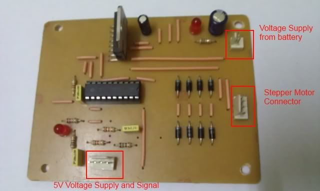
The bottom pins are +5V, direction signal, clock signal and GND from left to right respectively. The other functions of L297 like choosing full step, half step and wave step modes and the motor enable function are hard wired, and I've set it so that the motor is always enabled and the stepping mode is always in full step.

The LED near that pin is for the 5V supply to check if there is supply. It did save me troubleshooting time when I first hooked the driver up. The first time I hooked up the driver to my mainboard containing the microcontroller, that LED lit up and after 5-6 seconds, it gradually dim down until it finally turned off. As it turned out, my voltage regulator from the mainboard is overheating just from hooking up the driver. I slapped a heatsink at the regulator and it's smooth sailing from there.

The other supply at the top right of the circuit is the voltage supply directly from my battery for the stepper motor itself. I use 3-cell LiPo battery bought from here :lol: to power up the whole system. The LED near that connector serves the same purpose like the other LED but this one is for the voltage supply from the battery. The other connector is self explanatory I think.

Here's the rest of the photos.

Bottom surface of the driver
Image


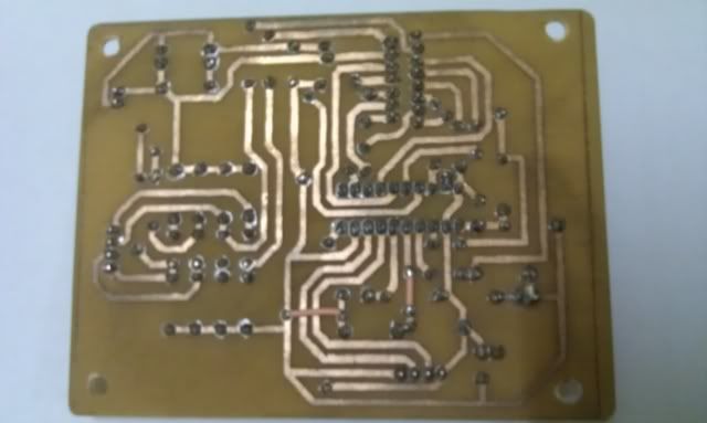
The driver in action
Image

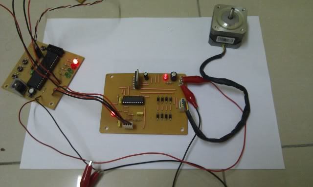
Somehow, photos aren't as effective in capturing the atmosphere of the driver in action here. I'd take a video if I can, but with my phone, it won't do much justice to it. So photos will have to do.

That is all. Thanks for watching.. and/or reading. :D
User avatar
Ffenixz
Freshie
 
Posts: 5
Joined: Sun Jan 23, 2011 1:20 am

Re: Stepper Motor Driver (L297+L298)

Postby robosang » Thu Jul 07, 2011 9:23 pm

Hey! Good work! So what is next ?
robosang
Expert
 
Posts: 1239
Joined: Wed Jun 10, 2009 5:37 pm

Re: Stepper Motor Driver (L297+L298)

Postby Ffenixz » Sun Jul 31, 2011 9:58 pm

Sorry for the late reply. What's next eh? Well I built another driver exactly like this one. With 2 stepper motors driven by the 2 drivers, they are then connected to the mainboard (you can actually see the mainboard in the last picture which the driver is connected to). I also connected 3 IR sensors (not shown) to the mainboard. Put all those on a platform and slapped a wheel each for the motor and I got myself a robot!

I was actually building a maze solving robot for a project. I know.. Waaaaaay too many projects of this kind already, but considering this is my first ever robotic project (while we're at it, my first electronic project too! :D), I thought I'd try something that is easily available on the internet (knowledge wise). I can say my first project is fairly successful. Still thinking about what to do for my next project. Cytron's quadcopter looks interesting. Maybe I'll look into that later after a few more projects to get myself more acquainted with microcontrollers and its various (x_X) peripheral communication protocols.
User avatar
Ffenixz
Freshie
 
Posts: 5
Joined: Sun Jan 23, 2011 1:20 am

Re: Stepper Motor Driver (L297+L298)

Postby robosang » Tue Aug 02, 2011 9:01 am

Good to hear that! Keep it up and don forget to share it :D
robosang
Expert
 
Posts: 1239
Joined: Wed Jun 10, 2009 5:37 pm

Next

Return to DC Motor

Who is online

Users browsing this forum: No registered users and 9 guests

cron