PR29
50 posts
• Page 1 of 5 • 1, 2, 3, 4, 5
Re: PR29
![]() by ABSF » Tue Feb 14, 2012 9:16 am
by ABSF » Tue Feb 14, 2012 9:16 am
Looks like you fixed everything except the problem! 
Have you programmed the PIC?
Are you sure all the wires on your breadboard are all correctly connected?
Is your power supply OK?
Is the +5V present on all the points that require it?
Is your LCD display tested working somewhere else?
These are just some of the things you have to find out before you insert your PIC onto the breadboard.
Post a picture would invite more help...
Allen
The next war will determine NOT who is right BUT what is left.
-

ABSF 
- Posts: 810
- Joined: Wed Nov 10, 2010 9:32 am
- Location: E Malaysia
Re: PR29
![]() by mark » Tue Feb 14, 2012 9:48 am
by mark » Tue Feb 14, 2012 9:48 am
Its quite a mess because I have to fix it on breadboard to show our lecturer that it's working then only we can solder it on pcb.
Have you programmed the PIC? Yes
Are you sure all the wires on your breadboard are all correctly connected? Yes, my lecturer took everything out and fix it and its still the same
Is your power supply OK? yes
Is the +5V present on all the points that require it? checked
Is your LCD display tested working somewhere else? i've tried
- Attachments
-
- mark

- Posts: 22
- Joined: Mon Feb 13, 2012 12:04 am
Re: PR29
![]() by ABSF » Tue Feb 14, 2012 11:41 am
by ABSF » Tue Feb 14, 2012 11:41 am
Your LCD covers up most of the things around the PIC which is an important part we want to see. Try to take the picture from the top instead of from the side.
Since you said the back lite is working, I assume the +5V is OK. Is your back lite too bright and the contrast of LCD too low that you're unable to see the text on it?
Do you have an Oscilloscope or logic probe for trouble shooting? The MCLR pin should be Low to High and stay High when +5V is applied to the PIC. The 8 wires from port B to the LCD DB0-DB7 should have good continuaty and the E and RS should detect pulses during activities. Since your PIC is programmed externally you may connect RB6 and RB7 directly to the LCD without going through 1K resistors.
During troubleshooting, you dont need the finger-print device so you may remove it temporarily to reduce the mess. Try to add 0.1uF on the +5V to gnd at the output of 7805.
Allen
The next war will determine NOT who is right BUT what is left.
-
ABSF - Posts: 810
- Joined: Wed Nov 10, 2010 9:32 am
- Location: E Malaysia
Re: PR29
![]() by shahrul » Tue Feb 14, 2012 5:29 pm
by shahrul » Tue Feb 14, 2012 5:29 pm
For me, make sure LCD part is function first. Because, the output is clearly tell what the status. So,
1. Check all the requirement supply voltage.
2. Check the LCD connection first
If me blank in this situation, I will take out first others component not related to LCD.
1. Check all the requirement supply voltage.
2. Check the LCD connection first
If me blank in this situation, I will take out first others component not related to LCD.
-
shahrul - Posts: 812
- Joined: Sat May 16, 2009 9:54 pm
- Location: Selangor
Re: PR29
![]() by mark » Tue Feb 14, 2012 9:53 pm
by mark » Tue Feb 14, 2012 9:53 pm
Since you said the back lite is working, I assume the +5V is OK. Is your back lite too bright and the contrast of LCD too low that you're unable to see the text on it? adjusted but only see black boxes
Do you have an Oscilloscope or logic probe for trouble shooting? The MCLR pin should be Low to High and stay High when +5V is applied to the PIC. The 8 wires from port B to the LCD DB0-DB7 should have good continuaty and the E and RS should detect pulses during activities. Since your PIC is programmed externally you may connect RB6 and RB7 directly to the LCD without going through 1K resistors. done
During troubleshooting, you dont need the finger-print device so you may remove it temporarily to reduce the mess. Try to add 0.1uF on the +5V to gnd at the output of 7805. done but still the same
- mark
- Posts: 22
- Joined: Mon Feb 13, 2012 12:04 am
Re: PR29
![]() by ABSF » Wed Feb 15, 2012 8:48 am
by ABSF » Wed Feb 15, 2012 8:48 am
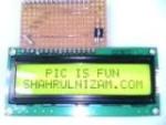
Should be hardware or wiring problem. I simulated the cct on Proteus and it worked. The text message appears for a few seconds and then shows a blank screen. It will appear again when the RESET is pressed.
Allen
- PR29 simulated on proteus
Allen
The next war will determine NOT who is right BUT what is left.
-
ABSF - Posts: 810
- Joined: Wed Nov 10, 2010 9:32 am
- Location: E Malaysia
Re: PR29
![]() by ABSF » Wed Feb 15, 2012 9:37 am
by ABSF » Wed Feb 15, 2012 9:37 am
Nop.... if you look at the software, after displaying the text, the 876a is sending command to the FP device and waiting for the reply. AFter the FP device replied, the message you mentioned would only then be displayed.
As i am unable to simulate the FP device, so my simulation just stopped there.
Allen
As i am unable to simulate the FP device, so my simulation just stopped there.
Allen
The next war will determine NOT who is right BUT what is left.
-
ABSF - Posts: 810
- Joined: Wed Nov 10, 2010 9:32 am
- Location: E Malaysia
50 posts
• Page 1 of 5 • 1, 2, 3, 4, 5
Who is online
Users browsing this forum: No registered users and 27 guests