Hi everyone,
I am going to build X10 home automation using pic16f877, my reference is AN236 from microchip.. It's just trying to duplicate what's in that datasheet. My Qs for those familiar with it are:
the datasheet explains the system referring to the power lines of 110VAC, so what possible changes can be done to run it on 240VAC?
my plan is to control few lamps, can I run them by connecting to the TRIAC side in direct way or must I get the x10 lamp module before in hand?
please refer to AN236
http://www.microchip.com/stellent/idcplg?IdcService=SS_GET_PAGE&nodeId=1824&appnote=en012050
Thank you,
Waddah
X10 home automation with pic16f877
15 posts
• Page 1 of 2 • 1, 2
Re: X10 home automation with pic16f877
![]() by zhenning » Thu May 03, 2012 5:19 pm
by zhenning » Thu May 03, 2012 5:19 pm
You need to do some modification. There is a transformerless power supply circuit which converts 110V to +5V 
- zhenning

- Posts: 351
- Joined: Thu Dec 30, 2010 12:32 am
Re: X10 home automation with pic16f877
![]() by waddah » Thu May 03, 2012 9:50 pm
by waddah » Thu May 03, 2012 9:50 pm
Thanks for your attention Zhenning,
The 5V is AC, isn't it ?
Another concern is the at the output side; that is the lamps.The thing is, I'm going to do a project for demo only, I'll do some wiring for few lamps for that purpose.
now, the datasheet mentions that there are Plug-in modules , among them lamp module, is it must to use them?
Regards,
Waddah
Waddah
- waddah

- Posts: 20
- Joined: Mon Nov 14, 2011 11:02 am
Re: X10 home automation with pic16f877
![]() by zhenning » Thu May 03, 2012 11:02 pm
by zhenning » Thu May 03, 2012 11:02 pm
The 5V is dc due to the diode, IN4005s. The zener diode is to keep the Vout to be at 5.1V DC. It's up to you how you want to do it
- zhenning
- Posts: 351
- Joined: Thu Dec 30, 2010 12:32 am
Re: X10 home automation with pic16f877
![]() by ABSF » Fri May 04, 2012 12:21 am
by ABSF » Fri May 04, 2012 12:21 am
I think it would be helpful if you read through this forum below. This person is doing the same project you're doing and he is from 230V ac country.
x-10 protocol and pic16f877 | CrazyEngineers
http://www.crazyengineers.com/community ... 877.28270/
Allen
x-10 protocol and pic16f877 | CrazyEngineers
http://www.crazyengineers.com/community ... 877.28270/
Allen
The next war will determine NOT who is right BUT what is left.
-

ABSF 
- Posts: 810
- Joined: Wed Nov 10, 2010 9:32 am
- Location: E Malaysia
Re: X10 home automation with pic16f877
![]() by waddah » Fri May 04, 2012 1:00 am
by waddah » Fri May 04, 2012 1:00 am
mmh, I was talking about the transformerless and thinking about the 0 crossing 
Anyway, I can replace that with batteries and v-regulators, right? I mean the the supply to the 5V components .
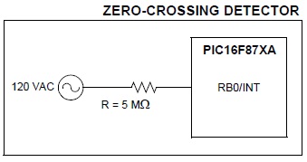
the datasheet explains that the system is plugged into a 110VAC/60Hz, the zero-crossing is necessary the limit the current(AC) before driving it to port RB0 for interrupt, I worry if the whole thing wont be compatible rather than dangerous for 240VAC/50Hz,?
Anyway, I can replace that with batteries and v-regulators, right? I mean the the supply to the 5V components .
the datasheet explains that the system is plugged into a 110VAC/60Hz, the zero-crossing is necessary the limit the current(AC) before driving it to port RB0 for interrupt, I worry if the whole thing wont be compatible rather than dangerous for 240VAC/50Hz,?
Waddah
- waddah
- Posts: 20
- Joined: Mon Nov 14, 2011 11:02 am
Re: X10 home automation with pic16f877
![]() by ABSF » Fri May 04, 2012 1:06 pm
by ABSF » Fri May 04, 2012 1:06 pm
waddah WROTE:mmh, I was talking about the transformerless and thinking about the 0 crossing
Anyway, I can replace that with batteries and v-regulators, right? I mean the the supply to the 5V components .
If you have a scope you can always check the input waveform before you put in the PIC. Or you may also put a 5.1V zener after the 5M resistor to prevent the voltage being too high.
Another way is to use a step down transformer (12V) and use the first half circuit as follows:
- picdccontrolleddimmer_1272130733(2).png (10 KiB) Viewed 5267 times
waddah WROTE:the datasheet explains that the system is plugged into a 110VAC/60Hz, the zero-crossing is necessary the limit the current(AC) before driving it to port RB0 for interrupt, I worry if the whole thing wont be compatible rather than dangerous for 240VAC/50Hz,?
For testing you can buy a 220V to 110V step down transformer and do everything on the secondary side of the transformer. This type of transformer is quite common for foreigners who migrated from countries using 100-120V AC. It can be bought from electrical or electronics shops. I got one which was used for my wire wrapping guns as they are all from Japan and US.
I also have a smaller one for my 100V color monitor.
When using 50Hz supply you have to amend the software to generate the burst at the correct interval as 50Hz is 20mS per cycle while 60Hz is 16.66mS per cycle.
Allen
The next war will determine NOT who is right BUT what is left.
-
ABSF - Posts: 810
- Joined: Wed Nov 10, 2010 9:32 am
- Location: E Malaysia
Re: X10 home automation with pic16f877
![]() by yonghui » Fri May 04, 2012 4:03 pm
by yonghui » Fri May 04, 2012 4:03 pm
be careful of HIGH voltage. Dangerous.
thanks®ards,
yh
yh
- yonghui
- Posts: 732
- Joined: Mon Sep 28, 2009 3:27 pm
Re: X10 home automation with pic16f877
![]() by zhenning » Fri May 04, 2012 4:07 pm
by zhenning » Fri May 04, 2012 4:07 pm
yonghui WROTE:be careful of HIGH voltage. Dangerous.
Yup. Especially, the transformerless ones
- zhenning
- Posts: 351
- Joined: Thu Dec 30, 2010 12:32 am
Re: X10 home automation with pic16f877
![]() by yonghui » Fri May 04, 2012 4:16 pm
by yonghui » Fri May 04, 2012 4:16 pm
hi,
from the app notes. seems like the load AC power supply need to be isolated from the main AC supply with isolation transformer so that the PIC can modulate the x10 carrier signal into the AC line.
regards,
yh
from the app notes. seems like the load AC power supply need to be isolated from the main AC supply with isolation transformer so that the PIC can modulate the x10 carrier signal into the AC line.
regards,
yh
thanks®ards,
yh
yh
- yonghui
- Posts: 732
- Joined: Mon Sep 28, 2009 3:27 pm
15 posts
• Page 1 of 2 • 1, 2
Who is online
Users browsing this forum: No registered users and 5 guests